Sunday, July 6, 2014

Small loop antennas (magnetic loops)


Built well, these small antennas perform really well.

Built well, only the bandwidth suffers as a result of miniaturisation.

  • Top left: 80m loop [3 x 1.5 x 0.8m], using 15mm copper tube.
  • Top right (and detail): 80 and 40m loop [1.8m x 1m x 0.8m], using 1m wide 1mm thick aluminium sheet.
  • Bottom: 160 and 80m loop [octagonal with 1.5m sides], using 28mm copper tube.

All these loops have integrated resonating capacitance. In the case of the sheet aluminium loop (top right) this is achieved by overlapping on one of the longer sides (see detail), with 8 or so nylon M6 bolts keeping the spacing resonably precise.

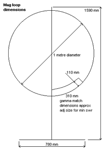
Coupling into the loop can either be by using a small loop within the main loop, or as shown, by tapping around the loop(via an isolating transformer, to allow the loop to float relative to ground). Using the tapping method gives a more obvious idea of loop impedance, and so has been used here. Calculating the capacitance value is easy enough: C(pF) = 0.0885A(square cm)/d(spacing in cm), giving 4425pF at 7MHz and 16 594pF at 3.7MHz. Ignoring effects due to the capacitors finite length, this corresponds to reactances of 5 ohms at 7MHz, and 2.72 ohms at 3.7MHz.

Assuming a constant current around the loop, the voltage across the capacitance is 5/1.45 x that across the feedpoint, which is 50 ohms. Thus for 100W drive, V = 70.7 x 5/1.45 = 244v. This gives the following loop current:

7MHz = 244/5 = 48.8A 3.7MHz = 244/1.7 = 100A

High currents are inevitable since the loop is not only much shorter than a quarter wave monopole, but being in phase, the two verticle section (say) currents are also in opposition (the radiatedsignal being a result of the small though finite difference between path lengths).

Return loss for loop tuned to 7MHz [-25dB at resonance]

Return loss for loop tuned to 3.7MHz [-32dB at resonance]

From these plots, you can see the 3dB bandwidth points (ie 6dB return loss) are 120KHz for the 7MHz antenna, and 30KHz for the 3.7MHz one. For solid state transceivers that have no output match tuning, this corresponds to an un-retuned operating range of about 60KHz at 7MHz (wide enough for the entire UK ssb segment) and 15KHz or so on 3.7MHz.

Using a remote tuner, these narrower figures could be trebled without incuring too much loss, but it would be sensible to use a coupling loop, not a ferrite transformer, if this is contemplated. A coupling loop circumference of 2.2m gave a good 50 ohm match when tried.

I tried to reduce the capacitor gap down to 2mm or so in order to resonate the loop on 1.94MHz, but even with a 1mm foam insulation, there was too much uneveness, and 2.45MHz was as low a frequency as could be managed,producing a 13KHz bandwidth as shown below:

I found 3mm foamed PVC ('foamalux') noticeably lossy - the bandwidth being 25KHzwhen tuned to to 2.45MHz (the 1mm foam used successfully was of unknown material).

This loop seems to work well enough on 3.7 and 7 MHz.

Notes on copper tube loops

With these, the trick is to implement the capacitance by reducing the tube diameter (from 28mm to 15mm, say) at one end of the loop, and putting a suitable length of this reduced diameter tube down the centre of the other (full diameter) end of the loop. So for example, the octagonal loop with 1.5m sides requires about 700mm of 15/28mm coaxial capacitance to resonate on 3.7MHz.For this particular antenna, I paralleled up six of the 1.5m lengths for the far side vertical (see pic) - all done using soldered copper fittings (except for the inners which used compression joints so as to be removable). With this arrangement, the loop easily tunes down to 1.9MHz.

That there are two closely spaced loops making up the octagonal antenna was done in attempt to reduce copper losses (prices for copper tubing greater than 28mm dia being very uncompetitive [in the uk, anyway])

The rectangular tube loop has four single loops in parallel, and uses 15mm tuning. The wide spacing was an attempt to reduce inductance and thus Q. Each of the four loops has a top horizontal that is actually coaxial (28/15mm), in order to achieve resonance. Individual capacitance also garrauntees equallity of loop currents. This antenna worked very well on 3.7MHz, but be warned, 15mm tubing is not very strong, and the loop will collapse under its own weight

Make a magnetic loop antenna for 7-21 mhz


  • Magnetic Loop Diagram

    Magnetic Loop Diagram

  • Magnetic Loop antenna

    Magnetic Loop antenna

This antenna has several advantages, not least being only 1 metre diameter! This loop relies on being horizontally polarised and receives only the magnetic wave, thus as most noise in the domestic environment is vertically polarised and electrical wave, it delivers low noise to your transeiver/receiver, which makes for nice clean listening. In addition any signal arriving in the direction of the loop end on will be nulled out, this can be useful to get rid of an interfering signal by simply rotating the loop leaving the desired signal in the clear. It can be used indoors with ease and works well at ground level which is not the case for long wire/dipole antennas at shortwave wavelengths.
So what are its disadvantages? Well its tuning is critical, such that for a small change in frequency the antenna will need to be retuned at the loop end. This is even more important for transmitting where a high reflected wave (swr) due to not being tuned correctly will damage the output stage of your transmitter! In addition due to the very high "Q" of the loop, very high voltages can build up on the loop tuning capacitor even with low amounts of power from your transmitter. It is for this reason I recommend this loop is used with a transmitter of no more than 8 watts, any more and the ordinary broadcast tuning cap will arc over with spectacular results. Of course should you wish, a higher spec/bigger air spaced tuning cap would allow higher power output transmitters to be used. Also I consider the use of remote tuning using a fairly high geared motor and insulated coupling on the tuning cap essential. For shortwave listeners manual tuning would suffice.
In setting up the tuning of the loop, connect to a receiver and tune to 14 mhz. Now tune the loop which as it nears peak tuning will cause a whooshing sound. Stop the tuning you should now hear good strength signals in your receiver. For tuning for a transmitter, 1st use receive method then apply low power and fine tune loop tuning and tweak gamma match for lowest swr.

Magnetic loop dimension details

  • Diameter of loop 1000mm
  • Diameter of tube 15mm
  • Width of base 780mm
  • Diameter of support pipe 42mm
  • Loop end spacing (for tuner) 50mm
  • Height of support 1590mm
  • Nylon board 210x240mm
  • Nylon board 240x70mm
  • Gamma match width 310mm
  • Gamma/loop spacing 110mm

Construction Tips

  • Use a bicycle wheel with no tyre on to help form the curves of the soft annealed copper tube
  • Clean the tube with wire wool before any soldering
  • Use a 100 watt soldering gun for the joints, but use a small blow torch first to get the copper at temperature to take a joint
  • Force some timber with the corners planed off down the plastic plumbing pipe this will stiffen the pipe as the loop is quite weighty
  • Use inverted shelf brackets to support the mounting pipe and make a wooden frame wide enough to hold up the loop

SMALL SINGLE TURN MAGNETIC LOOP


The small single turn magnetic loop (SSTML) antenna consists of a single winding inductor, about 3 feet (1 meter) in diameter, and a tuning capacitor. A second loop, which is one fifth of the diameter of the large loop, is connected to the feedline and this small loop is positioned in the large loop on the opposite side of the tuning capacitor.

Magnetic Loop Antenna

The SSTML has some very interesting properties:

a) It has a small footprint. The loop I describe here looks like a circle in the vertical plane and is just a little over 3 feet (1 meter) in diameter.

b)It is a rather quiet antenna. It doesn’t pick up as much man-made noise from nearby sources as a wire antenna would in the same situation.

c) This antenna is somewhat directional, which can benefit you in two ways. You can either aim (rotate) the antenna for maximum signal strength, or for minimum noise pickup. I prefer to do the latter, and here’s why. This antenna has what is called a deep null on each side of the antenna, the broad sides, meaning that signals coming from that direction will be attenuated quite a bit (30 dB is an often-quoted figure). However, this is mostly true for signals we receive directly, like noise sources, and not so much for signals from broadcast stations coming to us through skywave propagation. I aim the antenna for minimum noise pickup, which results in the best signal to noise ratio. In some situations it is quite possible to fully tune out a noise source such as a TV or computer monitor.

d) Since this antenna is really a tuned circuit, it also acts as a preselector. It only receives well in a narrow bandwidth of a few hundred kilohertz (kHz). The antenna requires retuning if you change the frequency on the radio by a hundred to two hundred kHz. This may sound like a disadvantage, but if you have ever tried a long wire antenna on a rather sensitive receiver, you probably have noticed that your receiver may get overloaded, resulting in hearing multiple stations at once or hearing broadcast stations on frequencies where there really aren’t any. This may make it impossible for you to pull in that DX station you’re really interested in or even make listening to a strong broadcast station rather unpleasant. This antenna will help prevent overloading your receiver.

Wednesday, July 2, 2014

A Shortened Inverted L for 160 Metres


Despite the dreadful noise on top band caused by modern electronic gadgets and the difficulty in accommodating a necessarily large aerial in a small garden, I was keen to try to get on to top band. I experimented with some different ideas during 2009, some of which are shown on this page.

Eventually I settled on the design shown below. It is an Inverted L type aerial, shortened by the use of a loading coil. It uses a fibreglass telescopic fishing pole to allow it to be easily lowered out of sight when not in use.  Read more on Antennas page 2 here>

Top Band Inverted L Aerial - shortened for small gardens - by M0MTJ

Shortened Base Loaded Top Band Antenna For Small Gardens
uses a fibreglass telescopic fishing pole to allow it to be easily lowered out of sight when not in use.

Saturday, June 28, 2014

QRP Power Meter and Dummy Load


Steve Yates - AA5TB

AA5TB Meter Photo 1

HOME

E-mail
Last Update: June 14, 2010

Many years ago I acquired a antique field strength meter and probe kit that did not function. However, the meter had a fast response time and a good enclosure and I thought it would make a good piece of test equipment. I designed the following circuit around what I had and it has worked out well for me.

The schematic below is of my QRP power meter and dummy (50 Ohm) load combination. The 50 Ohm load consist of resistors R2 through R5. The four 200 Ohm resistors in parallel combine to make 50 Ohms. I used four resistors because this minimizes the component lead inductance of the resistors as well as distributing the power dissipation. The meter is simply a current meter with a known internal resistance configured as an RF voltmeter. D1 rectifies the RF voltage across the load resistors and C1 charges to the peak of this rectified voltage. The capacitance of C1 is chosen so that the time constant of the RC circuit consisting of C1, R1 and the meter's resistance is long compared to the RF cycle. R1 is chosen so that when the RF power applied is 5 Watts the meter reads full scale.

QRP Power Meter and Dummy Load Schematic

The calculations are as follows:

Calculations

The internal resistance (Rm) can be found by constructing the simple circuit below and performing the following calculations:

Internal Meter Resistance

Adjust R until the meter reads it's full scale value. Be sure to start with R at it's maximum value to prevent damage to the meter. Solve the following equation to find the meter's internal resistance.

Internal Meter Resistance calculation

The formulae below are to convert the reading on the microampere meter to watts and back. Please note that the possible error caused by the diode's nonlinear response below about 100 mW has been ignored. The scale in the region of tens of milliwatts could be calibrated against a known calibrated power meter or signal source if desired. For more information regarding the very low power measurements with a diode detector you may want to check out "Square Law Diode Detectors in 50 ohm Systems" presented by Glen, VE3DNL.

Power Calculations

Current to QRP Power Conversion Chart

Current to QRPp Power Conversion Chart

Friday, June 27, 2014

Loop Antennas - Delta Loops and Square (Quad) Loops and more


Delta Loops for HF  -  "You'll love lower noise and relative gain over a dipole"
http://w5sdc.net/delta_loop_for_hf.htm
One Stealthy Delta - This HF antenna keeps a low visual profile while attracting plenty of attention on the air.
An excellent and amusing article by Steve Ford, WB8IMY
http://www.sgcworld.com/Publications/Articles/237qst0502.pdf
Random length multi-band delta loop antenna – A good antenna for when a dipole isn't enough by KC8AON
http://www.i1wqrlinkradio.com/antype/ch10/chiave1827.htm
An Easy to Install Vertical Loop for 80-6 Meters by John Reisenauer, Jr. KL7JR
http://www.hamuniverse.com/kl7jreasyvertloop.html
40m-10m DELTA LOOP ANTENNA - GU3WHN
http://www.rsars.org.uk/ELIBRARY/ANTENNAS%20DOCS/40m-10m%20%20DELTA%20LOOP%20ANTENNA%20-%20GU3WHN%20iss%201.3.pdf
M0PLK Multiband Delta Antenna - By Arthur M0PLK (SQ2PLK)
http://pdxa.one.pl/articles.php?article_id=17  available at http://ham-radio.urbasket.eu  and  http://www.vpa-systems.pl/
H5ANX Mk4 Delta Loop Design by Sajid Rahim
http://www.eham.net/articles/10738
Multiband H.F. Delta Loop by IW5EDI:
http://www.iw5edi.com/ham-radio/?dl2hcb-multiband-delta-loop,28
SGC Stealthy H.F. Delta Loop:
http://www.sgcworld.com/Publications/Articles/237qst0502.pdf
KL7JR Easy H.F. Delta Loop:
http://www.hamuniverse.com/kl7jreasyvertloop.html
H.F. Loop Antenna from Radioworks:
http://www.radioworks.com/nloop.html

W6ZDO Portable H.F. Delta Loop Project:
http://www.fros.com/KI0GU/w6zodelta.htm
Loop Antenna Notes by "Yukon John" KL7JR
http://www.hamuniverse.com/kl7jrloopnotes.html
Build a Multi-Band Mono Delta Loop for 40, 30, 20 and 15 Meters by Jose I. Calderon (DU1ANV)
http://www.para.org.ph/membersarticles/DU1ANV/Multi-Band%20Mono%20Delta%20Loop%20ant.pdf
DL2HCB Multiband Delta Loop
http://www.iw5edi.com/ham-radio/?dl2hcb-multiband-delta-loop,28
The Delta Loop (Skywire) Antenna - Legends, Theory and Reality
http://dk5ec.de/deltaloop-eng.htm
Loop Antenna notes and ideas from Radioworks
http://www.radioworks.com/nloop.html
Delta Loops by GW7AAV
http://www.cqhq.co.uk/2009_05_01_archive.html
More Delta Loop links:
http://www.i1wqrlinkradio.com/antype/delta_loop.html
Magnetic Loops:
Small Transmitting Loop Antennas (Magnetic Loop Antennas) by Steve Yates - AA5TB
http://aa5tb.com/loop.html

End Loaded Dipole


End loading can also help reduce the size of antennas, particularly useful for dipoles used on the  80m and 160m bands. An end loaded dipole will produce an antenna that is H shaped. There are several commercial designs available produced in designs that cover a single band and others that cover multiple bands. The version shown below is only 3 metres tall so will be suitable for very unobtrusive, low profile use. It is the ProAntennas Multi-band I-PRO: 20m 17m 15m 12m 11m & 10m which uses a capacity hat with some loading at the centre. http://www.proantennas.co.uk/

Other similar antennas were available from Force12 Antennas in the form of, amongst others, the Sigma 5 and Sigma GT5. The Sigma design used T-bars at each end of the vertical dipole for loading technique and off-center loading coils.  http://www.force12inc.com This was supplied supplied in the UK by Vine Antennas at one time http://www.vinecom.co.uk . Transworld Antennas also have produce antennaa using a similar concept - the TW2010 Adventurer and Backpacker http://transworldantennas.com

K9AY Notes that: "I have come to the conclusion from my experiments, readings and observations, that a capacity hatted vertical dipole, a few feet over ground, is less compromised than a 1/4 w/l vertical of the same height fed against a less than perfect ground. Let's face it, most amateur's ground systems are mediocre at best. Also, the dipole is easier and cheaper to rig, and is two dimensional..Very important in my situation, as I cannot run out radials on my neighbours property.  Or, to quote W4RNL.."Since only a handful of hams can ever have 160-meter antennas high enough to yield a low angle DX signal, more practical are vertical arrays such as yours.  Vertical dipoles with hats (or Tees) save a plethora of wire needed by monopoles." http://www.dxzone.com/cgi-bin/dir/jump2.cgi?ID=7466

K9AY
Information by K9AY

K9AY

Information by K9AY

K9AY

Interesting concepts from K9AY

The Norcal Doublet


Norcal Doublet Antenna
Norcal Doublet Antenna detail

The Norcal Doublet Antenna:  http://www.norcalqrp.org/norcaldoublet.htm

The Norcal Doublet is a simple antenna that is 44 feet (13.4 metres) long, 22 feet (6.7 metres) per side. The Norcal pages report "...that the antenna would have basically the same radiation patterns on all bands from 40 - 10 meters. This would be very handy to have for field operation..... You will need the following materials: 50 feet of 4 core stranded computer cable; 1 #0 Fishing Swivel; 1 Cable tie; 2 pieces of fishing cord."
The antenna can be hung from trees or cheap telescopic 'roach' / Sota poles. Doubling the size would allow operation on 80 metres and even 160 metres by shorting the twin feed together at the transmitter end and feeding it against a good earth as a 'Marconi' type antenna.

Wednesday, June 25, 2014

The Moxon-Beam


The Moxon-Beam was introduced by L. Moxon (G6XN) in his book "HF Antennas for all Locations" (RSGB- Publications, Great Britain 1993). This beam is a 2-Element-Yagi with radiator and reflector and reduced size to about 75% of a normal beam. The 2-Element-Yagi with reflector has normally a 0,2-lambda-boom and an impedance of 50 W. The Moxon-beam has a 0,18-lambda-boom and still 50 Ohm. This is a good impedance for wire- beams.The ends of the two elements are bended backward (radiator) or forward (reflector) and act as a capacitive load. That is much better than inductive loading with coils. So we have greater bandwidth and lower losses.Through the reduced size we get a 0,5-0,7 dB lower gain than with a fullsize beam.

This type of a 2-Element-Yagi has an unbelievable F/B-ratio on the design frequency of >= 30 dB. That is higher than with any other 2-Element-Beam.

The gain is higher on the beginning of the band and lower at the end. The bandwidth for a SWR < 1,5 is great enough for the range of 28,0-28,7 and 21,0-21,45 MHz if the beam is built up with aluminium tubes. Wire-beams of the Moxon-type have a smaller bandwidth.

The design frequency should be for a frequency 1/3 from the beginning of the band, because the SWR raises more below the design frequency. For example look for the SWR of a tube-Moxon for the 15-m-band:

Designing a Moxon- Beam is very easy with a useful little program by D. Maguire, AC6LA with the name "Moxgen".

This freeware can be downloaded at:

www.qsl.net/ac6la/

Moxgen generates an output file for "EZNEC" for modifications (e.g tapering) and shows you the dimensions for  building a wire-Moxon.

http://www.qsl.net/dk7zb/Moxon/Moxon.htm

Tuesday, June 24, 2014

MINI ATU WITH TOROID


This ATU was designed in about 1990 to allow QRP rigs to be used with portable antennas. The unit had to be small and light weight. Generally I am against using ATU's at all regarding them as a cop-out for poor antenna design. However, when portable operation is considered, it is not always possible to erect the ideal antenna. This ATU was designed with idea of achieving a better match to an antenna that was nearly right.

A later version was tried which had an additional coil switched in and also a balun to accomodate twin feeder. I was never happy with this version, as it didn't seem to work as well as the simple version. When it was deconstructed in 2007 to do some loss measurements, it was discovered that a constructional error during the mod may account for this.

ADRIAN KNOTT PROPOSES TUNED VLF ACTIVE ANTENNA


Hi to all! Today I found a very interesting project that using a small whip for hear the long VLF waves. Adrian Knot says that with this simple and inexpensive system you have good results, but suggests the using outdoor far from electric sources.
References: (http://www.hard-core-dx.com/nordicdx/antenna/special/vlfactive.html)

Low pass filter subwoofer using LM324

This is a low pass filter subwoofer using IC 324 and some other components. which is mr Kunal Banerjee sent to me to publish on our site.It is very useful Thank you very much The Schematic PCB LAYOUT ORIGINAL The PCB layout original PCB SILK ORIGINAL The PCB Silk original The components list //Capacitor/////////////////////// ———————————— […]

Putting up a Long-Wire Antenna


Fig. 2 Longwire antenna

Fig. 2 Longwire antenna


I've actually used this kind of antenna. When I was a teenager, I used it with my old Realistic stereo receiver to improve its AM reception, and it did work. (My dad put it up for me.)

Note: RadioShack sells this antenna as a kit, catalog # 278-758, $9.99 in their 2000 Catalog. You might also find it from other electronics suppliers. They sell the antenna wire as catalog # 278-1329, $6.99 in the same catalog. The insulators can be ordered for shipment to your house through RadioShack RSU catalog # 12099248, $4.79 + shipping in the 2000 Catalog.

Find two points, such as two poles (NOT utility poles!), or as most people will do, the corner of your house and a tree. Any safe places above the ground from which you can string this wire will do. Remember that not just the mounting places, but the "air-space" through which the wire will be strung must be free of obstructions, such as trees, and especially power lines. Whatever you do, don't put it on the same corner of the house through which your electrical service enters! First, that will be dangerous, and second, you'll pick up power line noise.

This antenna picks up signals best at right angles. It picks up worst end-on. Therefore, remember to orient the wire to pick up from the direction in which you are most interested.

Using an eye-hook at each point, attach a length of nylon rope. Tie the other end of the nylon rope to each insulator. The bare copper wire is strung from between the insulators, as shown in the diagram.

Use an insulated wire to connect to the copper wire at the end closest to your radio. Strip a couple inches of it and wrap it around the bare copper wire. For best results, solder this connection. This is shown in Figure 2. 

If you string the wire from a stationary point (such as a house) to a tree, use this trick that my father taught me, and that Ham Radio operators use. You see, the tree will sway in the breeze, stretching the wire over and over, eventually breaking it. So on the tree, instead of using a plain eye-hook, put up a pully (such as a clothsline pully). Run the nylon rope through this pully, letting a few feet hang down, and tie a brick (or suitable heavy weight) to the end of the rope. This is what I have illustrated in the first diagram. As the tree sways in the breeze, the rope moves feely through the pully, and the weight of the brick keeps the whole thing taut.

Grounding: From the ground terminal on your radio (next to the antenna terminal) run a wire to either a copper cold-water pipe (PVC pipe won't work) or a copper ground rod driven into the ground.

Some safety notes:

1. Keep your antenna far away from power lines! If you, your antenna or your ladder touches a power line, you could be KILLED.

2. Remember that you will be climbing ladders or trees to high place. Observe every safety precaution. Never extend the ladder beyond the manufacturer's reccomendation. Never stretch to reach a point-- instead, move the ladder. Have the ladder on a secure footing, and have someone there to hold the ladder.

3. Make sure your antenna is in a safe place, high enough so people or pets won't walk into it by accident. (Plus, the higher up you get it, the better it works).

4. Use lightening protection! Make provisions to disconnect and ground the antenna when not in use. C. Crane Company and RadioShack offer lightening protection devices. However, disconnecting and grounding the antenna is still the best option. RadioShack sells a simple knife switch you can use for this. Screw it to the wall or table next to the radio, hook one side to the antanna, the other to a wire leading to a copper grounding rod, or the copper cold-water pipe leading outside of your house. (Remember this doesn't work if you forget to throw the switch!)

Long Loopstick Antenna


Wound on a 3 foot length of PVC pipe, the long loopstick antenna was an experiment to try to improve AM radio reception without using a long wire or ground. It works fairly well and greatly improved reception of a weak station 130 miles away. A longer rod antenna will probably work better if space allows. The number of turns of wire needed for the loopstick can be worked out from the single layer, air core inductance formula:
Inductance = (radius^2 * turns^2) / ((9*radius)+(10*length))

where dimensions are in inches and inductance is in microhenrys. The inductance should be about 230 microhenrys to operate with a standard AM radio tuning capacitor (33-330 pF). The 3 foot PVC pipe is wound with approximately 500 evenly spaced turns of #24 copper wire which forms an inductor of about 170 microhenrys, but I ended up with a little more (213uH) because the winding spacing wasn't exactly even. A secondary coil of about 50 turns is wound along the length of the pipe on top of the primary and then connected to 4 turns of wire wound directly around the radio. The windings around the radio are orientated so that the radio's internal antenna rod passes through the external windings. A better method of coupling would be to wind a few turns directly around the internal rod antenna inside the radio itself, but you would have to open the radio to do that. In operation, the antenna should be horizontal to the ground and at right angles to the direction of the radio station of interest. Tune the radio to a weak station so you can hear a definite amount of noise, and then tune the antenna capacitor and rotate the antenna for the best response. The antenna should also be located away from lamp dimmers, computer monitors and other devices that cause electrical interference.

Magnetic loop antenna for 7-21 mhz

 
  • Magnetic Loop Diagram

    Magnetic Loop Diagram

  • Magnetic Loop antenna

    Magnetic Loop antenna

This antenna has several advantages, not least being only 1 metre diameter! This loop relies on being horizontally polarised and receives only the magnetic wave, thus as most noise in the domestic environment is vertically polarised and electrical wave, it delivers low noise to your transeiver/receiver, which makes for nice clean listening. In addition any signal arriving in the direction of the loop end on will be nulled out, this can be useful to get rid of an interfering signal by simply rotating the loop leaving the desired signal in the clear. It can be used indoors with ease and works well at ground level which is not the case for long wire/dipole antennas at shortwave wavelengths.

So what are its disadvantages? Well its tuning is critical, such that for a small change in frequency the antenna will need to be retuned at the loop end. This is even more important for transmitting where a high reflected wave (swr) due to not being tuned correctly will damage the output stage of your transmitter! In addition due to the very high "Q" of the loop, very high voltages can build up on the loop tuning capacitor even with low amounts of power from your transmitter. It is for this reason I recommend this loop is used with a transmitter of no more than 8 watts, any more and the ordinary broadcast tuning cap will arc over with spectacular results. Of course should you wish, a higher spec/bigger air spaced tuning cap would allow higher power output transmitters to be used. Also I consider the use of remote tuning using a fairly high geared motor and insulated coupling on the tuning cap essential. For shortwave listeners manual tuning would suffice.

In setting up the tuning of the loop, connect to a receiver and tune to 14 mhz. Now tune the loop which as it nears peak tuning will cause a whooshing sound. Stop the tuning you should now hear good strength signals in your receiver. For tuning for a transmitter, 1st use receive method then apply low power and fine tune loop tuning and tweak gamma match for lowest swr.

Magnetic loop dimension details

  • Diameter of loop 1000mm
  • Diameter of tube 15mm
  • Width of base 780mm
  • Diameter of support pipe 42mm
  • Loop end spacing (for tuner) 50mm
  • Height of support 1590mm
  • Nylon board 210x240mm
  • Nylon board 240x70mm
  • Gamma match width 310mm
  • Gamma/loop spacing 110mm

Construction Tips

  • Use a bicycle wheel with no tyre on to help form the curves of the soft annealed copper tube
  • Clean the tube with wire wool before any soldering
  • Use a 100 watt soldering gun for the joints, but use a small blow torch first to get the copper at temperature to take a joint
  • Force some timber with the corners planed off down the plastic plumbing pipe this will stiffen the pipe as the loop is quite weighty
  • Use inverted shelf brackets to support the mounting pipe and make a wooden frame wide enough to hold up the loop

Two transistors fm wireless microphone circuit

Two transistors fm wireless microphone circuit

This FM Wireless Microphone circuit Which adds a transistors in RF amplifier other one. So this circuit have two resonance circuits and also two trimmers. This cause have Higher efficiency And transmission far up.


Technical information.
  • Used DC Power supply of 9V

  • Maximum consumption current about 10mA

  • Transmission frequencies in the 88 MHz.

  • PCB dimensions: 1.64 x 1.54 inches.


  • The working principle.

    Two transistors fm wireless microphone circuit
    Figure 1 Two transistors fm wireless microphone circuit.
    The microphone acts as audio receiver, then will through C2 into base of TR1. Which the transistor will serves to RF generator. And is a mixed audio signal into frequency generated. By have T1 is the RF adjuster then mixed to send to C5 to base,to amplify RF out to collector to sending out the antenna. At collector of TR1, TR2 will have a copper wire as coil to instead general coil to easy to builds.

    How to builds its.
    components layout and wiring
    As Figure 2 the components layout and wiring of this project. I am sorry for cannot show PCB layout to you.

    FM wireless microphone circuit that assembly is completed
    Then Figure 3 FM wireless microphone circuit that assembly is completed.

    Testing
    To apply the 9 volts battery to the positive terminal (+9V) and negative (G terminal) for ANT point to connects to coil. They must be scraping the liquid coatings out the copper before soldering. Then FM radio stations to rotate positions 88 MHz using a plastic screwdriver to gently adjust the trimmer T1, Until it whistles howling out the radio.
    Next Try speaking into the microphone.

    However, if the experiment is no sound speakers. Turn the radio to about 100MHz. If this is not yet, turn the radio all the way to 108MHz and try again. Then, adjust T2 allows, in order to get more distance.

    The components list.
    R1, R2____________27K
    R3_______________4.7K
    R4_______________270 ohm
    R5_______________220K
    R6_______________470 ohm
    ELECTROLYTIC CAPACITOR
    C2_______________10uF
    CERAMIC CAPACITORS
    C1_______________0.022uF (223)
    C3, C6____________0.01uF(103)
    C4, C5____________3pF
    C7_______________5pF
    TRANSISTORS
    TR1, TR2_________2SC458, 2SC828, 2SC945, 2SC1815

    Friday, June 20, 2014

    Antenna for 432 MHz band with 21 dB gain

    Antenna Backscatter length 4L. Antenna is shown in Figure. The antenna has a gain of 21.4 dB
    with respect to increased half-wave dipole. The excitation system consists of a vibrator and a reflector nine directors. Reflector antenna configured as a disc whose diameter is equal to one wavelength. The vibrator has a length KL / 2. The first director is spaced a distance from the vibrator W-D1 = 0,2 L, each next - at a distance of 0,4 L from the previous one. The lengths of all Directors are equal (length director depends on its thickness). Full length of the excitation system is 4L. Large M reflector antenna has a diameter D, = 4L. In front of him at a distance of 0.25L. placed another ring-shaped reflector, the external diameter of which is 6L, and the internal - 4L. Studies have shown that this antenna has a gain of 8 dB greater than the antenna Uda-Yagi length 8L. Height w reflector ring is usually 0,25 L. Research has shown that an additional effect on the height of the antenna gain. The second figure shows the dependence of gain for one value of the diameter D = 2,35 L. Additional strengthening is added to strengthen that implements regular antenna is Backscatter flat reflector. An antenna with a large gain value for the 432 MHz band encounters certain difficulties, especially associated with the manufacture of a reflector of a sufficiently large diameter, since in this case it is necessary to ensure the necessary rigidity of the reflector and the carrying beam. Advantages of this antenna: high gain, power and simplicity of the relatively small size of the antenna criticality.


    antenna fo 432 mhz


    QRP Fan Dipole


    Fan Dipole Circuit The object of the exercise was to produce an aerial that would allow me to operate from 40 metres to 10 metres, specifically 40, 20, 17, 15 & 10 metres. The antenna was always going to be mounted in the attic as no external antennas are permitted at my QTH, the attic allows the antenna to 'beam' roughly northwest / southeast and the house is some 40 feet above sea level. Construction would be simplified by the fact that I intended to run a maximum of 10 watts which means that the antenna wires can be simply attached to the rafters. (Click on images for a larger version.)

    http://www.radiowymsey.org/FanDipole/fandiploe.htm

    Vertical antenna


    vantenna

    This type of antenna exhibits an omni-directional pattern, with a low radiation angle. The length of the radiator is calculated by using the formula 234/Frequency in Mhz, for feet, or 71.5/Frequency in Mhz, for meters to make a 1/4 wavelength, at the desired frequency. The radiator can be made entirely from 1" aluminum tubing, but can also be made from several sections of tubing of different sizes (Below 20M it is not appropriate to use 1" tubing). These could be fastened together using pipe clamps, after splitting the lower section about 1", across the circumference, along the diameter to facilitate clamping of the upper section.

    The radiator is mounted on a reasonable length square wooden post which is buried in the ground or fastened to the roof. Large diameter pipe clamps are used to fasten the radiator to the wooden pole. At about 1/2" from the base of the radiator a hole 1/8" should be drilled into the aluminum pipe. This hole is used for a bolt onto which the coax center conductor is fastened.

    The radials should be slightly longer than the radiator. To facilitate multi-band operation at least four radials should be used for each band you wish to operate in, the radiator being cut for the lowest band. All the radials are then fastened, or soldered together, and a connection is made to the coax cable shield. The radials should be buried a few inches into the ground, and ideally spread out in a circle. An antenna matching unit is used for multi-band operation. Alternatively, in place of aluminum tubing, a PVC pipe could be used, with a 1/4 wavelength wire positioned inside as the radiator. Note: For this antenna the Antenna Matching Unit should be at the base of the antenna, for best performance, and can be remotely controlled.

    A on-shot circuit ideals

    a-on-shot-circuit-ideals

    The digital circuit additional a circuits taht is very useful is On-Shots circuit or Also known as Mono-stable multivibrator circuit.

    This behavior is the input trigger signal into just a single pulse,which is usually a lot of thin or narrow. And then this circuit will output is pulse out there. But width of the pulse width can be set to a value more or less. As needed with configuring the device in circuits. There are several characteristics of this circuit, which I gather is the following.

    a-on-shot-circuit-ideals

    Simple Monostable Multivibrator by IC CD4528


    This the Simple Monostable Multivibrator circuit. That interesting by use IC CD4528 , be IC CMOS perform be Dual Monostable Multivibrator or One shot. When encourage at input make have a signal pecks at 2 output by have differently. Pulse duration and accuracy are determined by external timing components R1 and C1. Wide supply voltage range 3.0V to 18V. Separate reset available. Quiescent current e 5.0 nA/package (typ.) at 5.0 VDC.
    Diode protection on all inputs. Triggerable from leading or trailing edge pulse. Capable of driving two low-power TTL loads or one. Low-power Schottky TTL load over the rated tempera-ture rang.
    Simple Monostable Multivibrator by IC CD4528


    Two-Stage Timer By IC Dual Timer NE556


    This be Two-Stage Timer Circuit by IC Dual Timer NE556. Which 2 Timer both of build be One Shot. By wasp Trigger pin with GND. Timer1 work send pulse come out. enough be finished pulse. The this Timer2 as a result continue working replace. By the value Time bilateral control with R1,C1 and R4,C6.
    Two-Stage Timer By IC Dual Timer 556

    One-Shot By IC Quad Timer LM558


    When mention the circuit One Shot friends at take an interest digital side may know good that how much is it valuable ? And I thinks one part as a result like to use IC 555 for this work. Because of good easy economize with. But in occasionally you want to use One shot circuit. Many the group usual use IC 555 many may don't economize. Try use IC LM558 , replace see. Because integrated one circuit replaces IC 555 get 4 usability not very differently follow the circuit. Use a formula calculate same T = 1.1 RC when friends know like this a time tries to use integrated number this circuit ? be lucky sir.
    One-Shot By IC Quad Timer 558


    Simple Touch Switch One Shot by 4011


    Basic Timer By IC Quad Timer 558


    Today I begs for to advise the circuit timer the foundation. By use the integrated circuit number LM558 (IC Quad Timer). Which the structure within like to have IC 555 4 within. If think in the sense of the price has already. As a result economize very that one. For the usability have no differently IC 555 highly very popular extremely. Can use do timer circuit well sir time value can change with change R1 and C1 follow a formula calculates T = 1.1 RC good easy. friends try induce try build play request have fun electronics circuit.

    Basic Timer By IC Quad Timer LM558