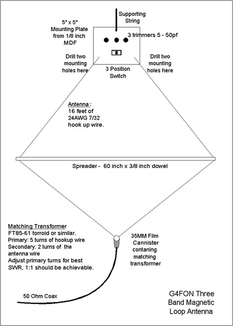
Described here is a simple multi-band magnetic loop antenna designed for 20, 30 and 40 metres, but by changing the overall length of the wire coverage of other bands is feasibleFor its size, the performance of the antenna always astounds me, although it is never going to replace a Yagi! The antenna is made from 16 feet of 24AWG 7/32 hook up wire. At the top of the antenna is a mounting plate which supports the three position band change switch and the three tuning capacitors. Each capacitor resonates the loop on one band. A piece of string is attached to the top of the mounting plate to support the antenna during operation. The matching transformer, at the bottom of the antenna, is wound on an FT50-61 torroid (this component does not seem too critical, but you may need to adjust the turns ratio, see later), which is housed in a 35mm film canister for protection. At the bottom of the film canister I have fitted a cable strain relief for the coax cable.
Construction
First mount the three position switch and the tuning capacitors on the mounting plate. At the top of the plate drill a hole for the supporting string, at the bottom of the plate drill two pair of holes in each corner to support the ends of the wire.
Measure 16 feet of hook up wire and find the midpoint by folding the wire back on itself. Pass the wire through the torroid and then pass one end through again to give two turns. Drill a hole on the opposite sides of the 35mm film canister and pass one end of the wire through each hole.
Drill a small hole about ½ inch from each end of the spreader and pass each end of the wire through one hole. Next pass the ends of the wire through the two holes in the mounting plate, making an overhand stitch pattern to act as a strain relief Put a bit of insulating tape on the antenna wire at the halfway point on each side to prevent the wire slipping through the spreader.
One end of the wire is connected to the common of the switch. Each position of the switch is connected to a single capacitor and the other side of the capacitors are commoned together and connected to the other end of the antenna wire.
Onto the ferrite torroid wind a further five turns of hook up wire and connect the ends to the coax cable.
Alignment
Aligning the antenna is straightforward, first set the switch to the first band position (20metres) and adjust the corresponding trimmer capacitor of maximum noise on receive. Move the switch to the second position and adjust the corresponding trimmer for maximum noise on 30 Metres. Repeat this for 40 metres. If you cannot obtain resonance on 40 metres, it may be necessary to add a second trimmer in parallel.
Once the antenna is roughly tuned, apply some RF through an SWR bridge and fine tune the capacitors for the lowest SWR on the QRP frequency of each band. Make sure you switch to receive while adjusting the trimmers as there are high voltages across the capacitors when on transmit.
Finally, experiment with the number of turns on the primary of the torroid to achieve the lowest SWR on all bands, switching between bands to check after each change. Changing the turns ratio may affect the resonant frequency of the loop.
If you have access to an antenna analyser, such as the MFJ range, then the job of final alignment is simplified.
No comments:
Post a Comment