-
G5RV antenna

THE G5RV ANTENNA
The G5RV is a very popular antenna on the HF amateur band today. Despite it's widespread use on the bands, there are some myths and misconceptions concerning the G5RV that seem to have a life of their own. Working with text from the ARRL "Antenna Compendium", Volume 1, I would like to shed some light on this versatile antenna.
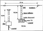
First, from Louis Varney, G5RV, of West Sussex, UK, here is some back- ground and insights into the G5RV. "The G5RV antenna, with its special feeder arrangement, is a multiband center-fed antenna capable of efficient operation on all HF bands from 3.5 to 28 MHz. Its dimensions are specifically designed so it can be installed in areas of limited space, but which can accommodate a resonably straight run of 102 ft for the flat-top."
Louis further states that, "In contradistinction to multiband antennas in general, the full-sized G5RV antenna was NOT designed as a half-wave dipole on the lowest frequency of operation, but as a 3/2-wave center-fed long-wire antenna on 14 MHz, where the 34 ft open-wire matching section functions as a 1:1 impedance transformer. This enables the 75-ohm twin-lead, or 50/80-ohm coaxial cable feeder, to see a close impedance match on that band with a consequently low SWR on the feeder. However, on all the other HF bands, the function of this section is to act as a "make-up" section to accommodate that part of the standing wave (current and voltage components) which, on certain operating frequencies, cannot be completely accommodated on the flat- top (or inverted-V) radiating portion.
The design center frequency of the full-size version is 14.150 MHz, and the dimension of 102 ft is derived from the formula for long-wire antennas which is:
LENGTH (ft) = 492(n-.05)/f(MHz)
= (492 x 2.95)/14.15
= 102.57 ft (31.27 m)
where n = the number of half wavelengths of the wire (flat-top)
"Because the whole system will be brought to resonance by the use of a matching network in practice, the antenna is cut to 102 ft."
As the antenna does not make use of traps or ferrite beads, the dipole portion becomes progressivily longer in electrical length with increasing frequency.
This effect confers certain advantages over a trap or ferrite-bead loaded dipole because, with increasing electrical length, the major lobes of the vertical component of the polar diagram tend to be lowered as the operating frequency is increased.
Thus, from 14 MHz up, most of the energy radiated in the vertical plane is at angles suitable for working DX.
Furtermore, the polar diagram changes with increasing frequency from a typical half-wave dipole pattern at 3.5 MHz and a two half-wave in-phase pattern at 7 and 10 MHz to that of a long-wire pattern at 14, 18, 21, 24 and 28 MHz.
Although the impedance match for 75-ohm twin-lead or 80-ohm coaxial cable at the base of the matching section is good on 14 MHz, and even the use of 50-ohm coaxial cable results in only about a 1.8:1 SWR on this band, the use of a suitable matching network is nessessary on all the other HF bands. This is because the antenna plus the matching section will present a REACTIVE load to the feeder on those bands.
Page 2 Thus, the use of the correct type of matching network is essential in order to ensure the maximum transfer of power to the antenna from a typical transceiver having a 50-ohm coaxial (unbalanced) output. this means unbalanced input to balanced output if twin-lead feed is used, or unbalanced to unbalanced if coaxial feeder is used.
A matching network is also employed to satisfy the stringent load conditions demanded by such modern equipment that has an automatic level control system. The system senses the SWR condition present at the solid state transmitter output stage to protect it from damage, which could be caused by a reactive load having an SWR of more than 2:1."
No comments:
Post a Comment