Steve Yates - AA5TB
E-mail
Last Update: June 14, 2010
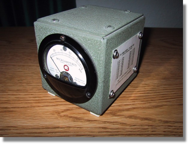
Many years ago I acquired a antique field strength meter and probe kit that did not function. However, the meter had a fast response time and a good enclosure and I thought it would make a good piece of test equipment. I designed the following circuit around what I had and it has worked out well for me.
The schematic below is of my QRP power meter and dummy (50 Ohm) load combination. The 50 Ohm load consist of resistors R2 through R5. The four 200 Ohm resistors in parallel combine to make 50 Ohms. I used four resistors because this minimizes the component lead inductance of the resistors as well as distributing the power dissipation. The meter is simply a current meter with a known internal resistance configured as an RF voltmeter. D1 rectifies the RF voltage across the load resistors and C1 charges to the peak of this rectified voltage. The capacitance of C1 is chosen so that the time constant of the RC circuit consisting of C1, R1 and the meter's resistance is long compared to the RF cycle. R1 is chosen so that when the RF power applied is 5 Watts the meter reads full scale.
The calculations are as follows:
The internal resistance (Rm) can be found by constructing the simple circuit below and performing the following calculations:
Adjust R until the meter reads it's full scale value. Be sure to start with R at it's maximum value to prevent damage to the meter. Solve the following equation to find the meter's internal resistance.
The formulae below are to convert the reading on the microampere meter to watts and back. Please note that the possible error caused by the diode's nonlinear response below about 100 mW has been ignored. The scale in the region of tens of milliwatts could be calibrated against a known calibrated power meter or signal source if desired. For more information regarding the very low power measurements with a diode detector you may want to check out "Square Law Diode Detectors in 50 ohm Systems" presented by Glen, VE3DNL.
No comments:
Post a Comment