
How it does works
As Figure 1 is the circuit diagram. To begin with R1 is connected to pin 7 and pin 8 of IC1. Which are the OSC1 and OSC2 pins will controls frequency of the oscillator circuit inside IC1. If value of R1 lower will be high frequency up. But R1's value is higher will be low frequency down.
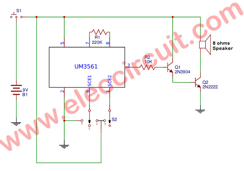
Figure 1 The circuit diagram of The 4 sound effect using UM3561
Then a choosing sound at appear at output will can select with the connecting of both pin SEL1 (pin 6) and pin SEL2 (pin 1) either pin to to positive or negative or all release.
1. If release pin 1 and pin 6 quietly the IC will emit the Police car sirens.
2. If we connect pin 1 (SEL2) to positive voltage (4th position) will get the Space Machine Gun Sound effect.
3. If pin 6 (SEL1) is connected to the positive (position 2) we will hear the fire truck siren.
4. But pin 6 is connected to negative voltage (position 3) will will hear the Ambulance sirens.
In selecting will connect either pin SEL1 or SEL2 only. When we selected pin SEL1 or ???? SEL2 then the controller circuit inside IC will send signal to control and command counter circuit to identify the location of data in memory. While sending data to the audio generator circuit. To make Tone of according to the data being recorded.
The tone will be sent to pin 3 of IC1 , then it will be increased by both transistors Q1 and Q2 through R2. Which serves to limit current bias both transistor, the signal strength to be able to output sound to the speakers. Or If this sounds like a lot, It can be connected signal from pin 3 of IC1 goes into a high-gain amplifier circuit as needed.
How to build.
This project we can assemble them on the perforated board as Figure 2 because there are a few parts.
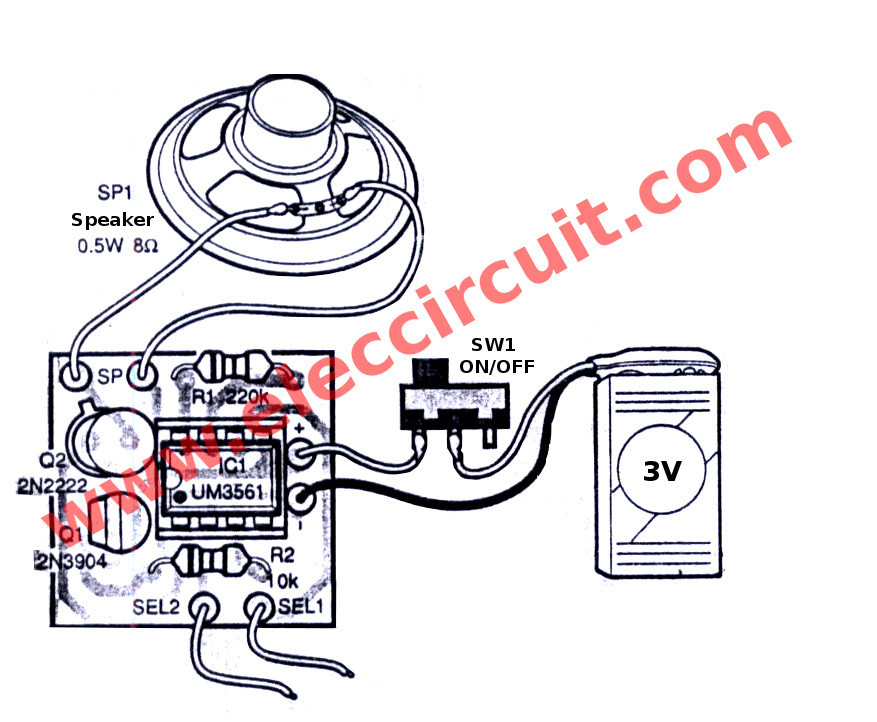
Figure 2 the component layout and wiring of 4 sound effect.
Figure 3 The project successfully been installed on the PCB.
I use a selector switch for select the sound output by I connecting wire as Figure 4
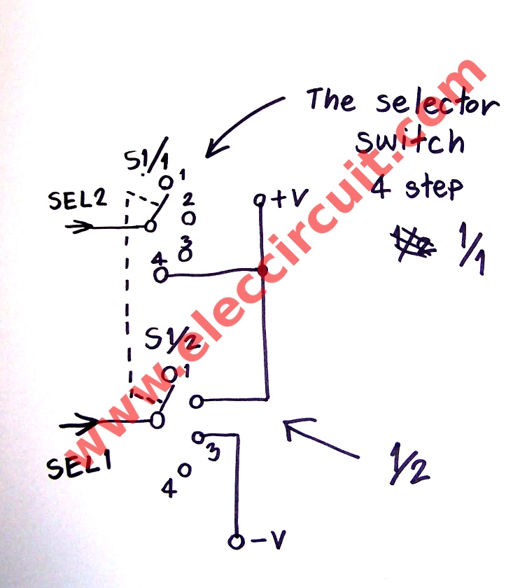
Figure 4 wiring the selector switch make we easy to choose tone output.
Applications
We can apply two AA 1.5 volts battery to supply of this circuit. If everything is OK Would have heard the Police car sirens out for sure. Then Then try the wires of lead SEL1 or SEL2,neither leg touches the positive, can signal one another.
Or can be modified in a theft or a kids toy. It does not rule any
As video below or Figure 5 is testing the projects
The part list.
Resistors 1/4W 5%
R1_________220K
R2_________10K
Semiconductors
Q1_________2N3904___NPN – transistor 0.5A 40V
Q2_________2N2222___NPN - transistor 0.8A 40V
IC1_________UM3561
Others
S1___Slide switch 3 lead.
S2___Selector switch 4 step.
Speaker 8 ohm 0.5W.
9 volts battery and snap connecter.
No comments:
Post a Comment