
Technical information.
The working principle.
Figure 1 Two transistors fm wireless microphone circuit.
The microphone acts as audio receiver, then will through C2 into base of TR1. Which the transistor will serves to RF generator. And is a mixed audio signal into frequency generated. By have T1 is the RF adjuster then mixed to send to C5 to base,to amplify RF out to collector to sending out the antenna. At collector of TR1, TR2 will have a copper wire as coil to instead general coil to easy to builds.
How to builds its.

As Figure 2 the components layout and wiring of this project. I am sorry for cannot show PCB layout to you.
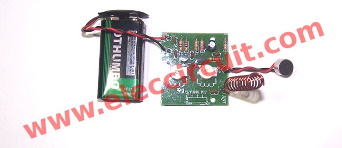
Then Figure 3 FM wireless microphone circuit that assembly is completed.
Testing
To apply the 9 volts battery to the positive terminal (+9V) and negative (G terminal) for ANT point to connects to coil. They must be scraping the liquid coatings out the copper before soldering. Then FM radio stations to rotate positions 88 MHz using a plastic screwdriver to gently adjust the trimmer T1, Until it whistles howling out the radio.
Next Try speaking into the microphone.
However, if the experiment is no sound speakers. Turn the radio to about 100MHz. If this is not yet, turn the radio all the way to 108MHz and try again. Then, adjust T2 allows, in order to get more distance.
The components list.
R1, R2____________27K
R3_______________4.7K
R4_______________270 ohm
R5_______________220K
R6_______________470 ohm
ELECTROLYTIC CAPACITOR
C2_______________10uF
CERAMIC CAPACITORS
C1_______________0.022uF (223)
C3, C6____________0.01uF(103)
C4, C5____________3pF
C7_______________5pF
TRANSISTORS
TR1, TR2_________2SC458, 2SC828, 2SC945, 2SC1815
No comments:
Post a Comment