
Technical information
Use power supply of 3 Vdc.
Maximum consumption current about 45 mA
PCB size : 2.38 x 1.24 inch.
How does it work.
A circuit diagram that shown in Figure 1 IC1 MK484 acts as receiver system by have variable capacitor and OSC coil as frequency adjusting of each station. The IC's OUTPUT will be connected to C3 to increase signal up by TR1 and TR2 sent to speaker .
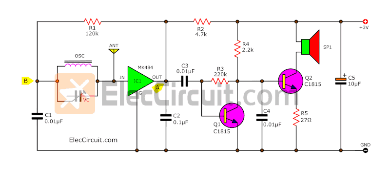
Figure 1 the circuit diagram of AM simplify radio with earphone
We use the general AM variable, The output is connected to a dynamic headphones or also small speakers. But impedance to 30 ohms up. The ANT point for the antenna.
Testing
The connecting to speaker SP point. Then apply 3V DC power supply to the circuit. The positive polarity to +3V point and the negative polarity to the G. Then we will hear sound on earphone. Radio station signal. But if can receive a few station. You can adjust the OSC coil and move ANT to antenna.
How to build
This project have a few we can assemble them on a universal PCB or solder on PCB as components layout and wiring in Figure 2

Figure 2 the components layout and wiring.
and Figure 3 is complete projects

Figure 3 The AM simplify radio ready to application.
The parts list
R1__________120K
R2__________4.7K
R3__________220K
R4__________2.2K
R5__________27 ohm
CREAMIC CAPACTTORS
C1, C3, C4____103 or 0.01uF
C2___________104 or 0.1uF
ELECTROLYTIC CAPACTTOR
C5___________10uF
IC
IC1___________MK484 or TA7642
TRANSISTOR
TR1, TR2______C458, C828, C945, C1815
No comments:
Post a Comment